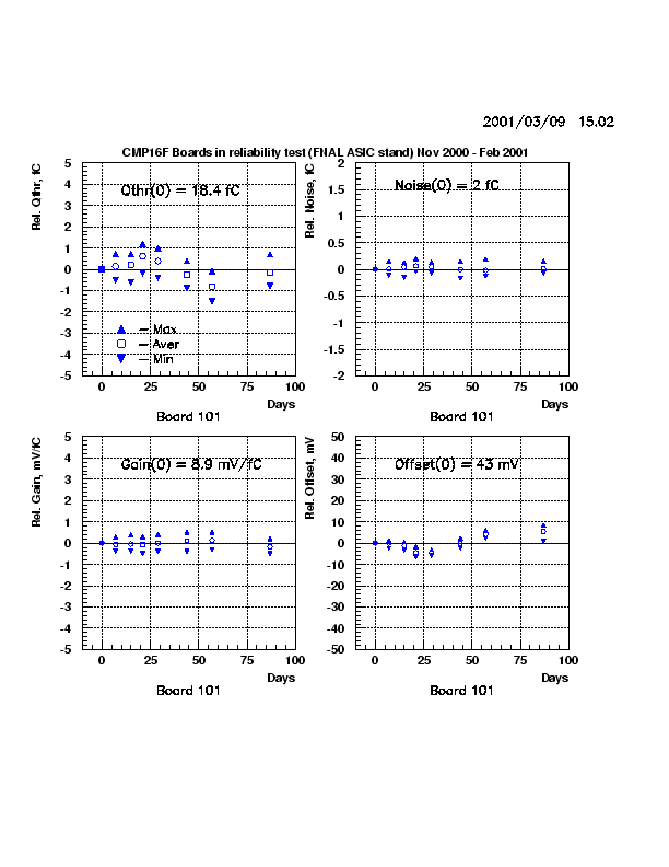
The parameters obtained from the data in run 0 for each channel in each
board were used as a reference. We calculated
the differences between the reference parameters and their values measured
in runs 1 - 7. The results have been averaged
over 16 channels for each board in each run. We also looked at the
maximum (as the most positive) and minimum
(as the most negative) values of these differences in each board
(see example for
Board 101 (*.ps),
Board 101 (*.gif)
).
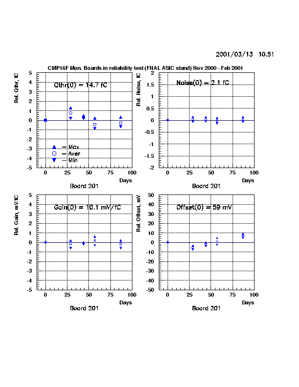
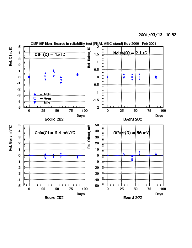
Two boards, 201 and 202, were kept outside of oven and were measured almost
each time (in Run 0 and then starting from Run 4)
together with the tested boards to watch the stability of the measurement
conditions, see
Board 201 (*.ps),
(*.gif)
and
Board 202 (*.ps),
(*.gif)
.
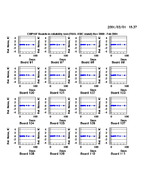
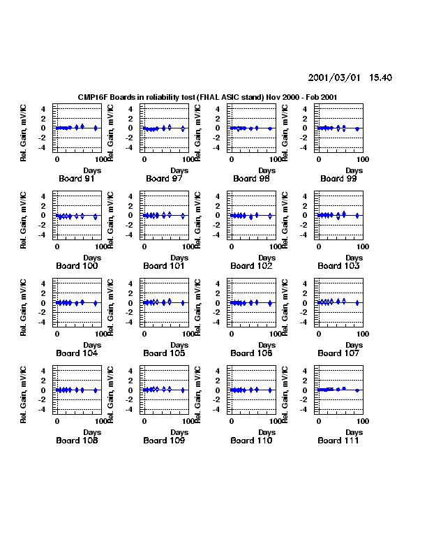
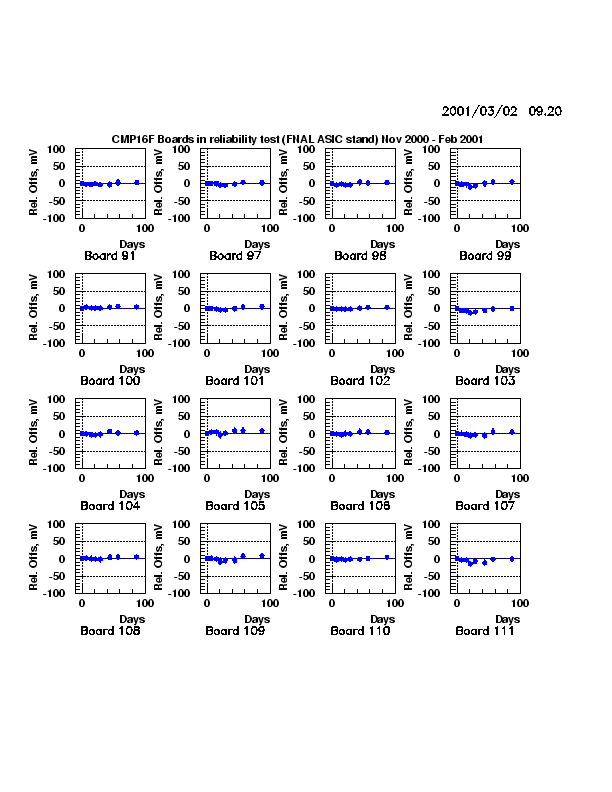
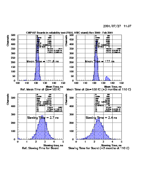
To monitor the variations versus heating time the results were plotted
for 99 boards board by board:
-
Fig.2a (*.ps),
Fig.2a (*.gif)
for changes in the threshold,
-
Fig.2b (*.ps),
Fig.2b (*.gif)
for changes in the noise,
-
Fig.2c (*.ps),
Fig.2c (*.gif)
for variations in the gain,
-
Fig.2d (*.ps),
Fig.2d (*.gif)
for discriminator offset changes,
-
Fig.2e (*.ps),
Fig.2e (*.gif)
for changes in the calculated chip internal Cinj.
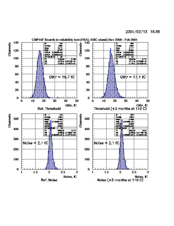
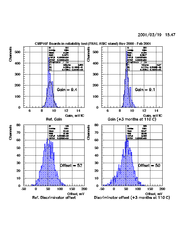
The threshold, noise, gain and offset distributions for all channels
together from reference Run 0 and Run 7
(after 3 months of heating) are here:
-
Fig.2f (*.ps),
Fig.2f (*.gif)
for threshold and noise,
-
Fig.2g (*.ps),
Fig.2g (*.gif)
for gain and discriminator offset.
The boards were practically stable during 3 months of heating at 110 C
degrees.
The deviations of the thresholds are less than +-2 fC. The noise remains
almost the same. There are some noticeable deviations
of parameters of a few boards in some runs mainly due to operator's
errors. For example, data for board 126 were mismeasured
in Run 0. Boards 136-145 in Run 7 have been powered up at the wrong
settings of the low voltage power supply.
Boards 161-162 have stable thresholds in Runs 1-7 and they are all
different from Run 0.
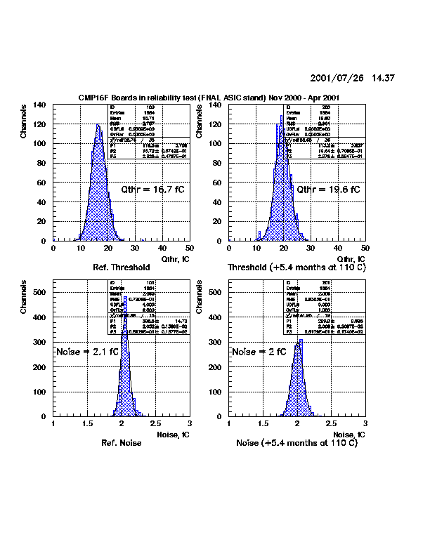
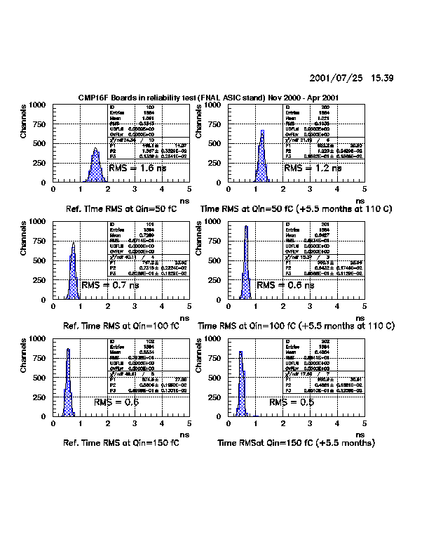
The threshold, noise, gain and offset distributions for all channels
together from reference Run 0 and Run 8
(after 5.4 months of heating) are here:
-
Fig.3a (*.ps),
Fig.3a (*.gif)
for threshold and noise,
-
Fig.3b (*.ps),
Fig.3b (*.gif)
for gain and discriminator offset.
Note for Run 8 the shift in the offset and gain resulting in the shift of
the threshold by 3 fC. The monitoring boards 201 and 202 show the same effect.
The data in Run 8 were taken on the new test stand having different hardware.
In particular a new pulse generator was used with the pulse rising time of
10 nsec instead of 40 nsec as it was in runs 0-7. Indeed, using old generator
on the new stand we observed the shift of the threshold of 2 fC. Therefore the
data from Run 8 also confirm the stability of parameters of the boards after
5.4 months of heating. No new dead channels were found.
|